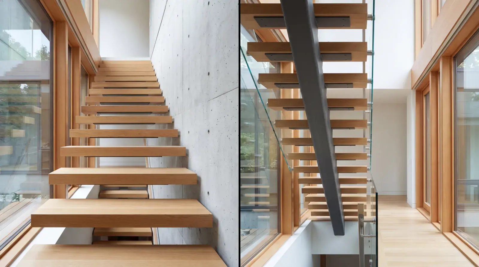
Mono stringer and cantilevered staircases both solve a specific design problem, support treads in space while leaving the view through the stair open. The visual result is similar. The structural logic is completely different, and those differences drive every downstream decision about materials, fabrication, and installation.
This is a fabricator’s technical comparison of how each system actually works structurally. It is pitched at architects, engineers, and sophisticated homeowners who want to understand why one system costs more than the other, why retrofits are harder for one than the other, and why the engineering guide for mono stringer staircases reads the way it does.
Two systems, two load paths
A mono stringer acts as an inclined structural beam. The combined dead load (self-weight of steel, treads, railings) and live load (occupants and any applied loads) is transferred through the beam to two end connections, one at the top floor, one at the bottom floor. The beam experiences bending along its length, with maximum bending moment near the midspan and maximum shear at the end supports. The beam must be sized for flexural capacity, shear capacity, and deflection.
A cantilevered staircase has no spanning beam. Each tread is its own small cantilever, anchored into a wall at one end and projecting free at the other. The load on each tread creates a bending moment at the wall connection that tries to rotate the tread downward. The tread and its bracket must resist the moment force, and the wall must resist the cumulative rotational forces from all the treads that anchor into it.
From a load-path perspective, the two systems are opposite. The mono stringer consolidates loads and sends them to two end points. The cantilevered system distributes loads at every tread and concentrates moment forces into a wall along the full stair length.
Quantifying the forces
For a residential stair with 14 treads, 275 mm tread depth, 195 mm riser, and a 9-foot 6-inch floor-to-floor, here is how the forces break down on each system.
Mono stringer analysis:
- Span along the stringer: approximately 3.8 m (along the slope)
- Horizontal span: approximately 3.3 m
- Distributed live load along the stringer: 1.9 kPa × (tread width / cos θ), typically 1.8 kN/m
- Concentrated live load: 1.5 kN at any point
- Stringer self-weight and dead load: typically 0.8 to 1.2 kN/m for HSS 8x4 or similar
Design for a 14-tread stringer of this size typically results in an HSS 8x4 to 12x6 beam at 3/8 to 1/2 inch wall thickness, selected to meet both strength and deflection (L/360) requirements. The engineer runs the calculation using CSA S16 - https://www.csagroup.org as the governing design standard.
Cantilever tread analysis:
- Tread projection from wall centre: approximately 340 mm (half of a 680 mm tread plus wall offset)
- Concentrated live load at tip: 1.5 kN per BC Code
- Uniform live load over tread area: 1.9 kPa
- Factored bending moment at wall: approximately 0.75 kN-m per tread under concentrated load with load factor
That moment has to be resisted at every single tread. Across 14 treads, the cumulative moment transferred to the wall is substantial, approximately 10.5 kN-m before load factors. The wall reinforcement has to resist the combined forces, which is why the engineer typically specifies a continuous steel channel or plate running the full height of the stair.
The individual bracket design is also non-trivial. A bracket that has to resist 0.75 kN-m of moment and transfer it into a bolted or welded connection to the wall backing steel requires careful plate sizing, bolt pattern design, and weld detailing.
Deflection behaviour
Mono stringer deflection is beam deflection, predictable, calculable, and controllable through beam sizing. The engineer sizes the beam so that midspan deflection under full live load does not exceed L/360 (typical residential serviceability limit). For a 3.8 m span, that is about 10 mm maximum deflection at midspan. In practice, engineers often design to L/480 or better to ensure the stair feels absolutely rigid.
Deflection along the stringer is smooth and uniform. A person walking up the stair experiences a small, continuous deflection under their weight. No tread flexes independently, the whole beam flexes together by a small amount.
Cantilevered tread deflection is concentrated at each tread. Under a 1.5 kN concentrated load at the tip of a 340 mm cantilever, the tread tip deflection depends on the bracket stiffness. A well-designed cantilever bracket will limit tip deflection to a few millimetres. A marginal design allows deflection that is perceptible when walking up the stairs, the tread moves under foot.
This is why cantilevered stairs sometimes feel “flexy” even when structurally adequate. The deflection is concentrated at the point of load application. The solution is overdesign of the brackets and the wall reinforcement, which is why cantilevered systems use more steel than mono stringers.
Connection design
Mono stringer end connections are two critical connections, top and bottom. Each connection has to transfer the reaction force from the stringer into the floor structure. For a typical residential mono stringer, the reaction at each end is approximately 10 to 15 kN under factored load.
The bottom connection is usually a steel base plate anchored to concrete or through-bolted to reinforced framing. Anchor bolts are sized to resist shear and tension (the stringer can try to both slide and lift under load). The top connection is typically a bracket bolted through the floor structure to a reinforced header or a structural steel beam.
Both connections are designed for the full reaction force with appropriate safety factors. The structural drawings specify bolt sizes, grade, pattern, and torque.
Cantilevered bracket connections are numerous and demanding. Every tread bracket has to resist the moment force at its wall connection. Typical brackets are fabricated from 10 to 16 mm steel plate, welded into a rigid bracket shape, and bolted through the wall into the backing steel.
The connection detail is critical. A bolt pattern that is adequate for shear but inadequate for moment will allow the bracket to rotate under load. The engineer typically specifies a minimum of four bolts per bracket in a pattern designed to resist the moment couple. Bolt size, grade, and spacing all feed the structural calculation.
Welding quality matters enormously on cantilevered brackets because they carry concentrated load through welded plate assemblies. CSA W47.1 certified welding - https://www.csagroup.org is required, and visible structural welds on brackets must meet AWS visual inspection standards (no cracks, undercut within tolerance, proper throat thickness).
Wall and floor reinforcement
This is where the systems diverge most dramatically.
Mono stringer reinforcement is localized at the two end connections. The top connection usually requires a reinforced header or beam at the upper floor, this can be a steel member, an engineered lumber header, or a reinforced rim joist. The bottom connection requires either a concrete slab with adequate edge distance for anchor bolts, or a reinforced floor framing pocket. Reinforcement is local, the floor framing 2 m away from the connection is unaffected.
Cantilevered stair reinforcement runs the full height of the stair. A typical detail is a continuous steel channel (HSS or C-section) running from the bottom landing to the upper landing, with every tread bracket through-bolted to the channel. The channel transfers all the rotational forces from the brackets into the wall framing. The wall studs must be sized to resist the continuous horizontal load on the channel and the vertical loads from the tread brackets. In new construction, framers install the channel before closing the wall. In retrofits, the wall has to be opened, channel installed, and wall closed back up.
This fundamental difference in reinforcement approach is why cantilevered retrofits are hard and mono stringer retrofits are comparatively easy.
Material quantities
For a comparable 14-tread residential stair, approximate steel quantities:
Mono stringer: Stringer beam (75 to 125 kg), tread brackets (14 × 3 kg = 42 kg), base plate and top connection hardware (15 kg), railing posts (40 to 60 kg). Total structural steel: approximately 170 to 240 kg.
Cantilevered: Individual tread brackets (14 × 8 to 12 kg = 112 to 168 kg), wall reinforcement channel (45 to 70 kg), base and top connection hardware (10 kg), railing (similar to mono stringer, 40 to 60 kg). Total structural steel: approximately 200 to 290 kg.
Cantilevered systems use more steel per stair. The brackets are heavier, the wall reinforcement adds substantial material, and fasteners are more numerous. This is a key driver of the cost difference between the two systems.
Fabrication implications
Mono stringer fabrication is centered on the single long beam. The beam is cut to length, tread brackets are welded to it at precise locations, base plate is welded at the bottom, top connection bracket is welded or bolted at the top. Quality control is straightforward, the beam is one object, shop tolerances are easy to verify.
Cantilevered fabrication is fourteen small objects plus a wall reinforcement channel. Each bracket is cut, welded, ground, and checked individually. Installation tolerance is much tighter because each bracket has to align with the next one in both horizontal and vertical planes. Shop fabrication for a cantilevered system is more labour-intensive than for a mono stringer of equivalent size.
Installation comparison
Mono stringer installation is typically 2 to 3 days: stringer placement day 1, treads day 2, railings day 3.
Cantilevered installation is typically 3 to 5 days: bracket placement and alignment day 1, bracket check and adjustment day 2, treads day 3, railings days 4 to 5. The extra time is primarily in bracket alignment, getting 14 brackets all plumb, level, and on the exact centrelines specified in the drawings.
When each system wins
Mono stringer wins when:
- The stair does not sit against a continuous structural wall
- The project is a retrofit into an existing home
- The stair includes L-shape, U-shape, or curved geometry
- Budget matters and the goal is visual openness rather than zero visible structure
- The schedule is tight (less coordination with framing)
Cantilevered wins when:
- The stair sits along a structural wall in new construction
- The framing schedule allows pre-installation of wall reinforcement
- The design intent requires zero visible structure below the treads
- Budget supports the additional steel, engineering, and installation complexity
- The geometry is a straight run
For most residential applications in Metro Vancouver, mono stringer is the more flexible and cost-effective answer. Cantilevered systems are a specific architectural move that needs the right conditions to succeed.
See the comparison guide for a broader comparison across other stair types as well.
Code and standards
Both systems are designed under the same standards:
- Structural design: CSA S16 (Canadian steel design standard) - https://www.csagroup.org
- Welding: CSA W47.1 (certification required for any structural weld)
- Loads: BC Building Code, Part 4 structural design loads - https://www2.gov.bc.ca/gov/content/industry/construction-industry/building-codes-standards/bc-codes
- Serviceability: L/360 deflection typical for residential, often tightened to L/480 in custom work
- Geometry: BC Building Code Part 9 (residential) or Part 3 (commercial) for tread, riser, guard, and headroom requirements
A P.Eng. stamp is required on the structural drawings for either system before a building permit is issued in Metro Vancouver.
What this means for a project decision
For a homeowner, architect, or contractor weighing mono stringer vs cantilevered for a specific project, the decision drivers are:
- Is there a structural wall the stair can anchor into? If no, mono stringer by default.
- Is this new construction or a retrofit? If retrofit, mono stringer is almost always the right answer.
- Is the geometry straight, or does it include a direction change? Mono stringer handles L-shape and U-shape; cantilevered does not (without hybridizing).
- Is the budget tight or generous? Mono stringer is more cost-effective; cantilevered carries a meaningful premium.
- Is the architectural priority structural honesty (visible steel) or structural invisibility (treads from a wall)? Pick the system that matches.
For most Metro Vancouver residential projects, the answer is mono stringer. For the specific subset of projects where cantilevered is the right answer, get the engineering and coordination right from schematic design.
Request a quote with your project details and we will walk through the structural approach that makes sense for your specific situation.