If you’ve received structural engineering drawings for a building project in Metro Vancouver, the connection details probably look more complicated than you expected. Thicker plates, more bolts, full-penetration welds with inspection requirements, stiffener plates that seem redundant, all of it is there because of where we build.
Metro Vancouver sits in one of the highest seismic hazard zones in Canada. The Cascadia subduction zone runs along BC’s coast, and the 2020 National Building Code assigns peak ground acceleration values of 0.40g to 0.50g to sites across the Lower Mainland. Those numbers drive every structural steel connection we fabricate at our Burnaby shop.
This post walks through what your engineer is actually specifying on those connection details, the types, the logic behind them, and what they mean on the fabrication floor.
Connections are where earthquakes test a building
During an earthquake, the ground shakes sideways. A building’s structural frame needs to transfer those lateral forces from the roof down to the foundation without the connections giving out. The members themselves, beams, columns, braces, are sized to resist the forces. But the connections between those members are where the load path is most vulnerable.
A well-designed steel member can bend, flex, and yield without sudden failure. Steel is ductile, it deforms before it breaks. But a connection that’s undersized, under-welded, or poorly detailed can fail in a brittle manner. The beam might be fine, the column might be fine, but if the bolts shear or the weld cracks at the joint, the frame loses its load path and the floor above has nothing holding it up.
That’s why CSA S16, the Canadian standard for structural steel design, dedicates extensive provisions to seismic connection detailing. And it’s why engineers in Metro Vancouver spend more time on connection design than engineers in low-seismic parts of the country.
Moment connections, making the frame rigid
The most common seismic connection type in steel buildings is the moment connection. Where a standard shear connection allows the beam-column joint to rotate freely (a “pin”), a moment connection makes that joint rigid, the beam and column move together as a unit.
In a moment-resisting frame (MRF), every beam-column joint with a moment connection contributes to the building’s lateral resistance. When an earthquake pushes the building sideways, the rigid joints prevent the frame from racking into a parallelogram. The beams bend, the columns bend, the connections transfer forces between them, but the frame holds its shape.
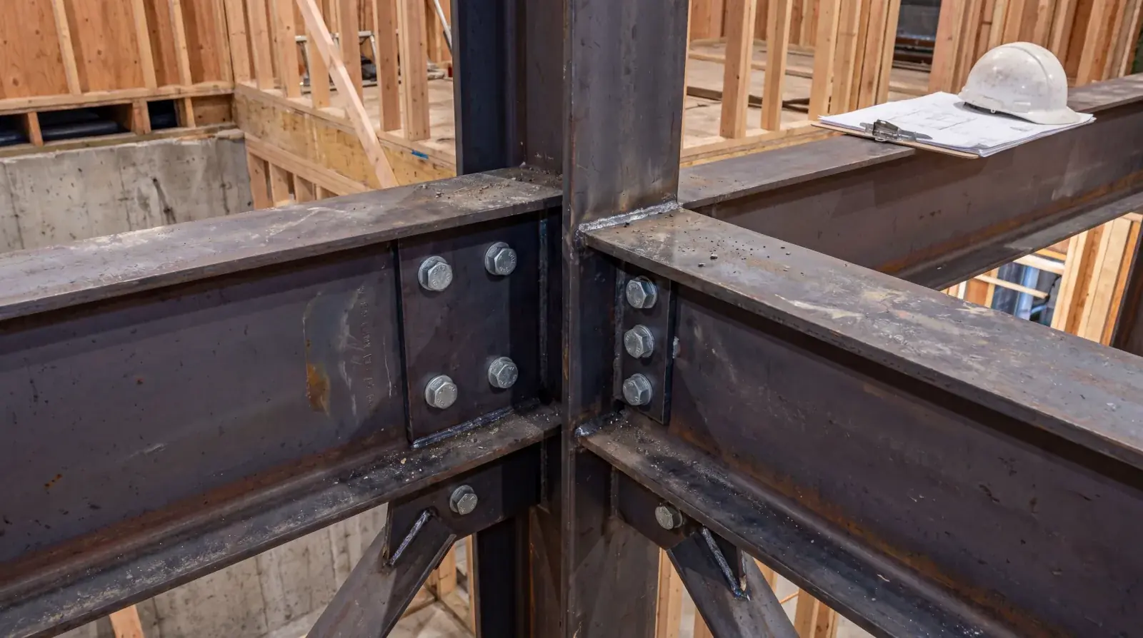
What this looks like in steel: a moment connection at a beam-to-column joint typically includes bolted or welded flange plates connecting the beam flanges to the column flanges, stiffener plates welded inside the column web at the beam flange levels (continuity plates), web connection (shear tab or plate) transferring the vertical load, and potentially web doubler plates on the column if the panel zone is overstressed in shear.
A single moment connection might involve 8 to 15 individual plates, 20 to 40 structural bolts, and a dozen or more shop welds including CJP (complete joint penetration) welds on the flange connections. Compare that to a simple shear tab, one plate, three bolts, and you understand why seismic detailing drives fabrication time and cost.
Ductile vs. conventional, a design choice with real fabrication impact
CSA S16 defines several categories of seismic force resisting systems (SFRS), each with different ductility requirements and corresponding design force levels. The two most relevant for steel buildings in Metro Vancouver:
Ductile moment-resisting frames (Type D MRF) are designed so that during a major earthquake, controlled plastic deformation (yielding) occurs in specific locations, typically the beam ends near the column face. The connections must be strong enough to develop the full plastic moment capacity of the beam, forcing the yielding to happen in the beam rather than the connection. This “strong connection, weak beam” philosophy means the building absorbs earthquake energy through beam yielding rather than connection failure.
The fabrication impact: bigger welds, thicker plates, and more stringent weld quality requirements. CJP welds on beam flange connections are standard, with mandatory ultrasonic testing to verify full fusion. Column continuity plates must be full-depth and fully welded. The steel grade and mechanical properties of every plate and member need to be verified against mill certificates, because the capacity hierarchy (connection stronger than beam, column stronger than beam) depends on actual material properties, not just nominal values.
Conventional construction (Type CC) has less stringent ductility requirements but compensates with higher design forces, typically 2 to 3 times the seismic force used for a ductile system. The connections can be simpler (fewer plates, smaller welds), but the members themselves are heavier because they’re designed for higher forces without relying on ductile energy dissipation. For smaller buildings and residential projects, Type CC can sometimes be more economical because the connection detailing is simpler, even though the beams and columns are larger.
Your structural engineer selects the SFRS type based on building height, layout, cost optimization, and the architectural constraints of the project. From our perspective as the fabricator, we need to know the system type early because it fundamentally changes how we detail and weld every connection in the package.
Braced frame connections
Not every building uses moment frames. Braced frames, structures with diagonal steel members that resist lateral forces, are common in BC construction, especially in buildings where architectural flexibility is less of a concern than economy.
In a concentrically braced frame (CBF), diagonal braces connect at the beam-column joints through gusset plates. The brace can be an HSS tube, a wide-flange section, or angles, depending on the engineer’s design. During an earthquake, braces in tension yield (stretch) while braces in compression buckle. The connection at each end of the brace needs to handle both conditions without tearing apart.
Gusset plate design is where the engineering gets detailed. The gusset, a thick steel plate, usually 12 to 25 mm, connects the brace to the beam and column. The gusset geometry follows specific rules: the Whitmore section width determines the gusset’s capacity in tension, and the fold-line length (the distance from the brace end to the nearest re-entrant corner) must allow the brace to buckle out-of-plane without fracturing the gusset. Engineers calculate these dimensions per the procedures in CSA S16.
For the fabricator, gusset plate connections are weld-intensive. The gusset is welded to the beam flange and the column flange (or web), and the brace is welded or bolted to the gusset. The welds between the gusset and the frame members are often CJP or large fillet welds sized to develop the full capacity of the gusset. On a moderately braced frame, six to eight braced bays, the gusset plate connections can represent 30 to 40% of the total fabrication labour in the steel package.
Weld quality on seismic connections
Seismic connections live or die on weld quality. The 1994 Northridge earthquake in California exposed catastrophic failures in moment connections where beam flange welds cracked during the earthquake, connections that had been designed and built to the existing code. The post-Northridge research changed how moment connections are detailed and welded across North America.
The key weld-quality requirements on seismic connections in BC:
CJP welds on beam flange-to-column connections. The weld must fuse the full thickness of the beam flange to the column flange. Any lack of fusion, an internal defect where the weld metal didn’t bond to the base metal, creates a stress riser that can initiate a crack during cyclic earthquake loading.
Backing bar removal. In pre-Northridge practice, the steel backing bar used to facilitate the CJP weld was left in place after welding. Post-Northridge research showed that the notch between the backing bar and the column flange acted as a crack initiator. Current best practice, and many engineers in BC now require it, is to remove the bottom flange backing bar after welding and apply a reinforcing fillet weld to eliminate the notch.
Weld access holes. The shape and surface finish of the weld access holes (cutouts in the beam web that allow access for flange welding) are specified to minimize stress concentrations. The access hole geometry follows CSA S16 requirements, and the cut surfaces must be ground smooth.
Ultrasonic testing (UT). CJP welds on seismic moment connections typically require 100% UT inspection by a certified inspector. The UT report verifies full fusion through the weld depth and identifies any internal defects that would compromise the connection’s performance under cyclic loading.
All of this happens within our CWB quality program. Every welder in our Burnaby shop who performs seismic connection welds is individually certified for the positions and processes required, overhead CJP welds on thick flanges are a different qualification than horizontal fillet welds on thin plates. The CWB certification under CSA W47.1 ensures those qualifications are current and audited.
Reduced beam section (RBS) connections
One of the post-Northridge innovations that shows up regularly on Metro Vancouver steel projects is the reduced beam section, or RBS connection, colloquially called a “dogbone” because of the shape it creates.
The concept: instead of making the beam flange-to-column weld strong enough to force yielding into the beam span (which requires very heavy, expensive connections), the beam flanges are deliberately trimmed in a specific radius cut at a short distance from the column face. This reduced section creates a controlled weak point where the plastic hinge will form during an earthquake.
Why it works: the plastic hinge moves away from the column face weld, the location where Northridge-era connections failed. The reduced flange area ensures yielding happens in the beam flange metal (which is ductile) rather than at the weld (which is less ductile). The radius cut is machined to a smooth profile to avoid stress concentrations.
What it means in fabrication: the RBS cut is typically made with a CNC plasma cutter or a router jig that follows a calculated radius. The cut surfaces are ground smooth to a specified surface finish. It’s additional fabrication labour, but it allows the engineer to use lighter connections, which can offset the RBS fabrication cost on buildings with many moment connections.
What the fabricator needs from the engineer
A common friction point on seismic steel projects is incomplete connection details on the structural drawings. The engineer specifies the connection type (moment, shear, braced) and the force demands, but the full fabrication detail, plate sizes, bolt patterns, weld sizes, access hole geometry, sometimes isn’t developed until the shop drawing stage.
For our shop to produce efficient, accurate shop drawings, we need the following from the engineer’s design package: the SFRS type and design parameters (ductility category, Rd and Ro values), beam and column sizes with grades, connection type at each joint (moment, shear, braced), force demands at each connection (shear, moment, axial), weld inspection requirements (which welds get UT, what acceptance criteria), and any project-specific requirements (backing bar removal, RBS specifications, bolting method).
When this information is clear and complete on the engineer’s drawings, shop drawing development runs quickly and the RFI count stays low. When it’s incomplete, we’re issuing RFIs and waiting for responses, which adds time to the schedule before fabrication even starts.
From the engineer’s drawing to the finished connection
The journey from a connection detail on paper to a welded assembly in our shop involves multiple quality checkpoints that exist specifically because of BC’s seismic requirements.
The engineer designs the connection. Our detailing team produces shop drawings with full fabrication detail. The engineer reviews and approves the shop drawings. We procure material and verify grades against mill certificates. Welders, certified for the specific positions and processes, fabricate the connections following CWB-qualified welding procedures. Internal quality control inspects every structural weld. Third-party UT inspection is performed on specified CJP welds. The completed assembly is marked, documented, and shipped.
Every step in that sequence traces back to a BC Building Code requirement or a CSA S16 provision. It’s not paperwork for its own sake, it’s the chain of verification that ensures the connection will perform as designed when the ground shakes.
If you’re working on a project with seismic steel connections in Metro Vancouver and need a CWB-certified fabricator who understands these requirements, contact our shop. We’ll review your engineer’s drawings and scope the fabrication, see more of our structural connection work.